Blog
February 16, 2022
How To Install Tigo Dedicated Rapid Shutdown Devices


Rapid Shutdown requirements
Let's talk about the TS4-F and 2F, but first let's talk about what the code says in the United States about rapid shutdown because like it or not, that is going to start spreading outward and it will start influencing other directives and requirements outside the United States.
US requirements:
- Requires rapid shutdown within 1ft of the array for all new rooftop PV systems
- The inverter and the shutdown device must be tested (ULPVRSE) and certified together (UL PVRSS)
- For all new rooftop installations across most of the US
The whole rapid shutdown initiative was to protect first responders – people that show up on the scene when there's a structural fire – and the whole point is to protect them so that they won't get shocked if they have to mess around with the array.
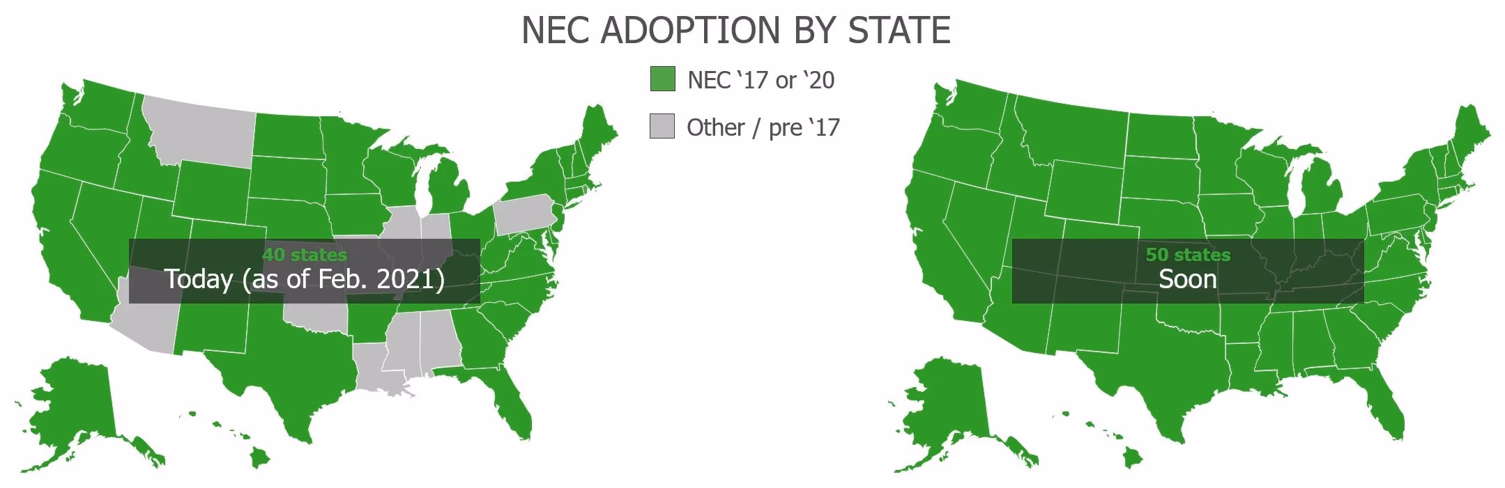
This first came out in 2014 and the code writers just slapped a bunch of stuff in the code. You can tell they really didn't think about it, they just wanted to get something in the code. Then over the years they've refined it. As they refine the code, more and more systems keep adopting newer and newer versions of it. So as of today, there are 40 states that are NEC ‘17 or newer.
Like I said earlier, it's reading through other countries. Matter of fact, I got a text from a lady that I've known for a while – she's up in Manitoba – and she's like, “Hey, I need to get my hands on some TS4-F. Where can I go?” It's like, wow, it's already going everywhere.
TS4-A-F and 2F
Let's talk about the TS4-F and then we also have its partner product, the TS4-2F. I leave the ‘A’ out because we've pretty much gotten away from the TS4 that are mounted on the module – the ‘A’ stands for add-on, which means you just install it right on the module, but just for brevity, I call them F or 2F.
.gif)
Components for this system
- Rapid shutdown device (RSD)
- An initiation device, which we call the RSS transmitter
- String inverter
The architecture
You have to have the component up on the roof, the TS4-F and 2F. Then, the RSS. Now the RSS transmitter can either be external to the string inverter, or it can be internal – it can be integrated. And we do have a list of integrated manufacturers so that makes it even easier; one less thing to have to install.
We can see in Figure 2 flipping it around that the F are mounted directly to the module and the 2F will take an input from two different modules. So, you cut down on the number of things that you have to buy and install, although these things do go in really easily. Then in this example, I'm showing an RSS transmitter that's integrated into this inverter.
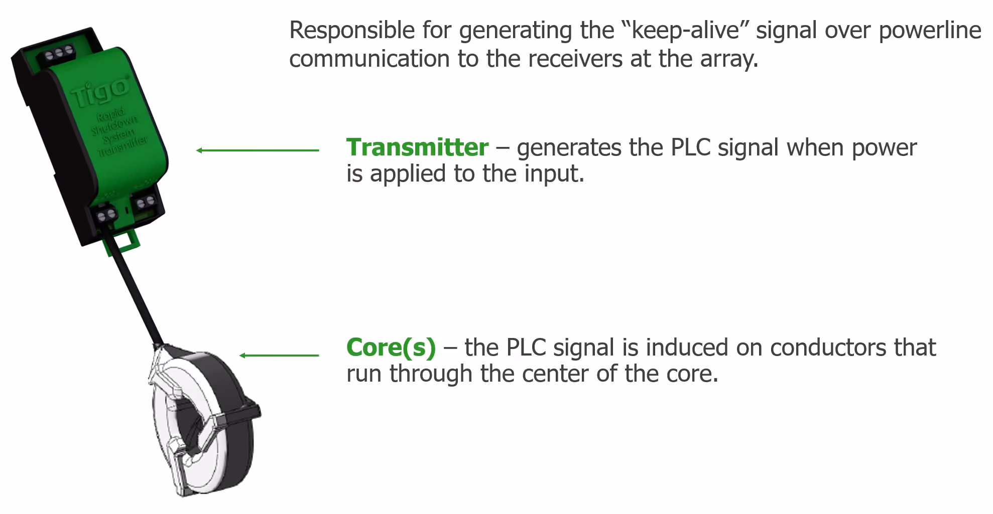
So, let's talk about this transmitter for a second. We did an update to this thing right after I started working at Tigo. If you're familiar with it, you can see in Figure 3 that the core down here now has two colors. So that's going to help you guys with the polarity as you put the conductors in there.
The transmitter induces, or it creates this keepalive signal– some people call it a heartbeat signal – and it goes into the core, which then induces this signal onto the PV homerun wires that are put through it.
That signal goes across the PV lines called powerline communication – it's a very popular form of communication – and the TS4 up on the roof are waiting to hear this keepalive signal. And if they receive it well, then they allow the module power to flow through them down through the DC lines, into the homeruns, into the PV inverter; works fine, last a long time, everybody's happy. When the TS4 do not detect this keepalive signal, they stop allowing the PV to pass through them.
Now the TS4-F and 2F acts as the receiver. It's either going to be in operation or it's going to be in shutdown mode. And again, TS4-Fconnects to one module. The 2F connects to two, and there are some differences in specs. There’s 700W for the F and 1,000 Watts for the 2F but it's 500 per channel. So, we're talking about module size. 16 to 90 volts, 15 amp are the same and we use MC4 standard connectors. And if you want, you can put a to 2F and F you can mix and match them if you want to do that.
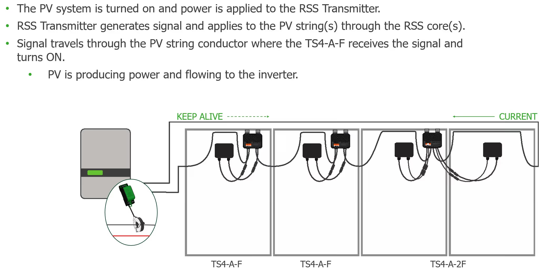
Figure 4 shows a visual wrap-up of what I just talked about. You can see that the homeruns go through the core and all the homeruns, either the positive or the negative conductors, must run through this. As long as the TS4receive the keepalive signals, then they will pass that current down to the inverter.
Installation
Let's talk about the installation. These things are ridiculously easy to install. They clip right on and takes 10 seconds per install, very easily.

You can see the clips in Figure 5, these little silver things, and that's really all you do – you clip it up onto the frame and move on. Now, if you are using frameless modules, which look super cool, you can still use these. You will pop those clips off with a little screwdriver, and then you would just bolt the TS4 onto the rail.
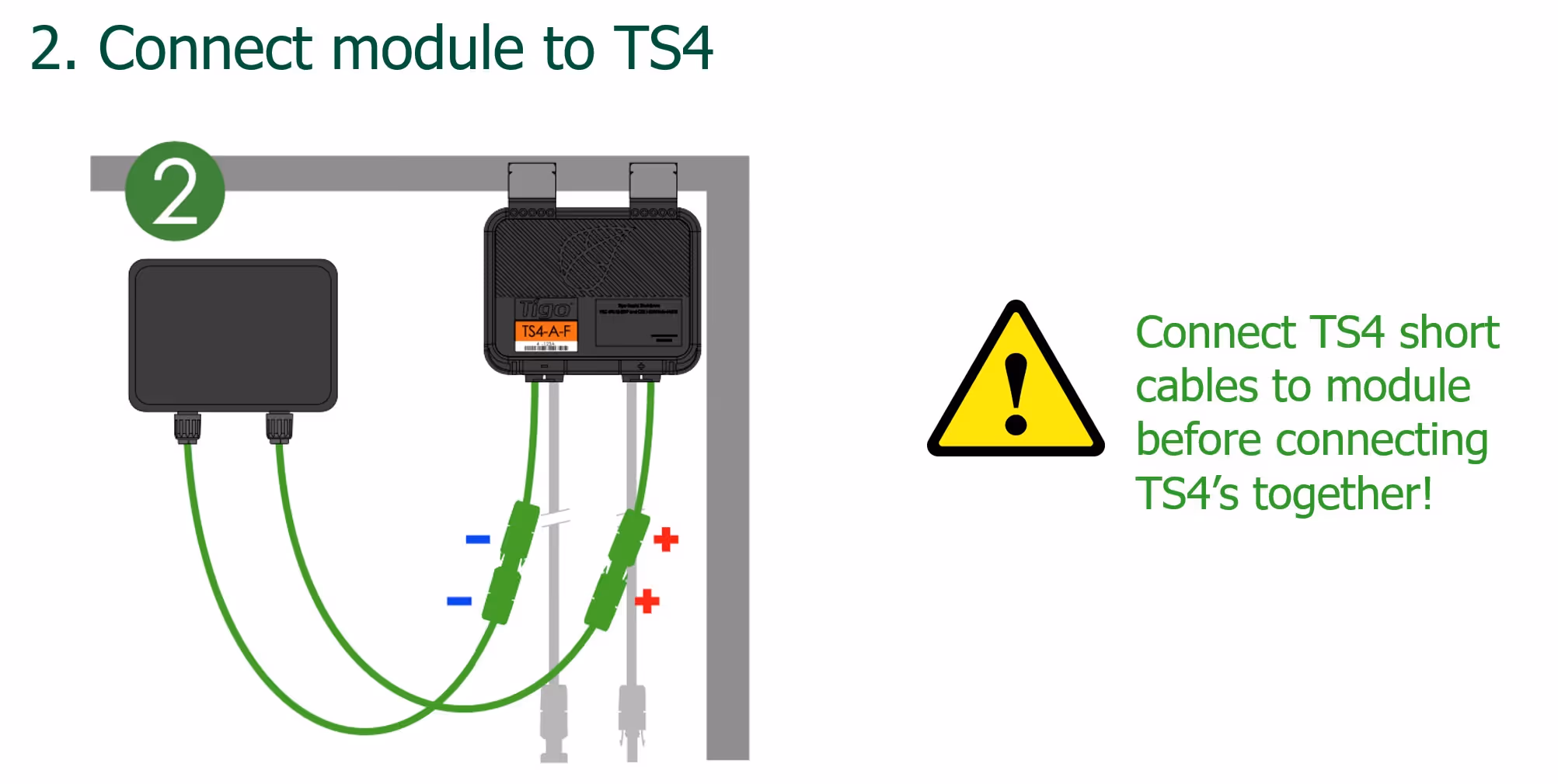
Now, what we want to do is connect the module leads to the TS4,and there's two different leads on the TS4: these short ones and then you have long ones. So, we're going to start with the shorties. You will always attach the module to the short TS4 leads first, always. And this is a little bit different, we do get calls people coming in because they didn't follow this. So please, this is the order of operation.
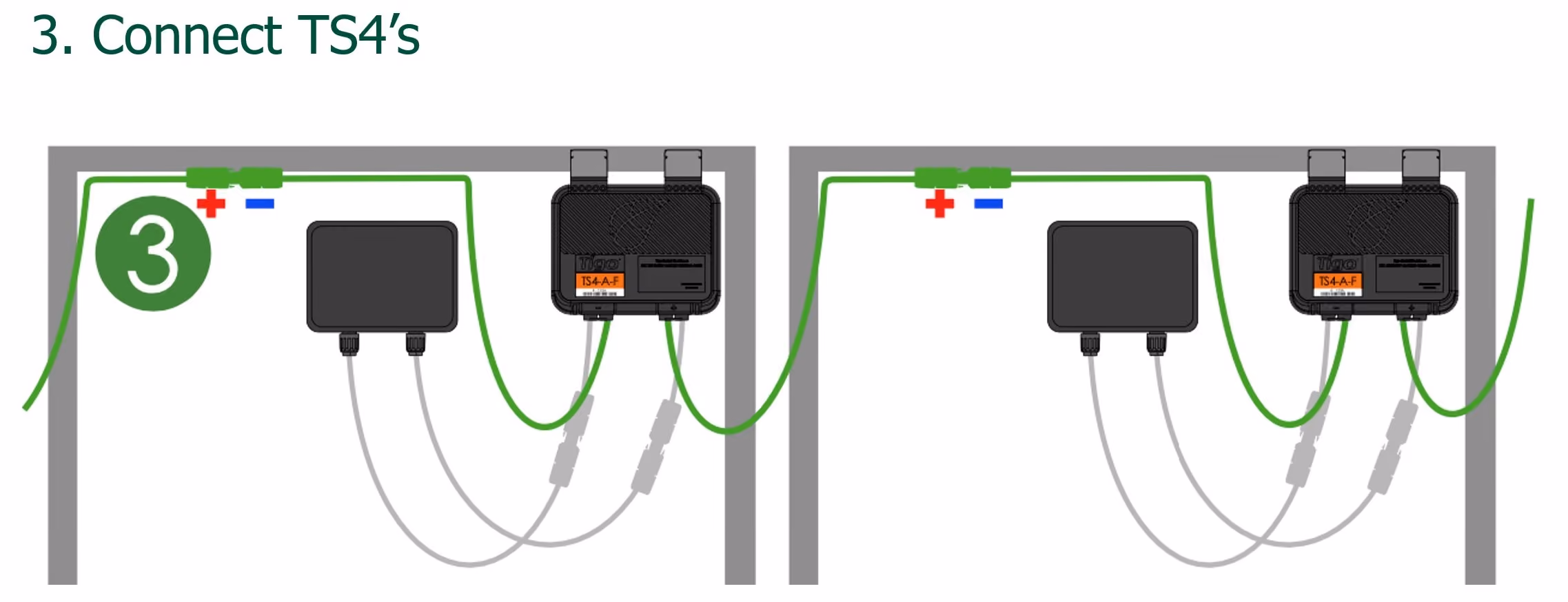
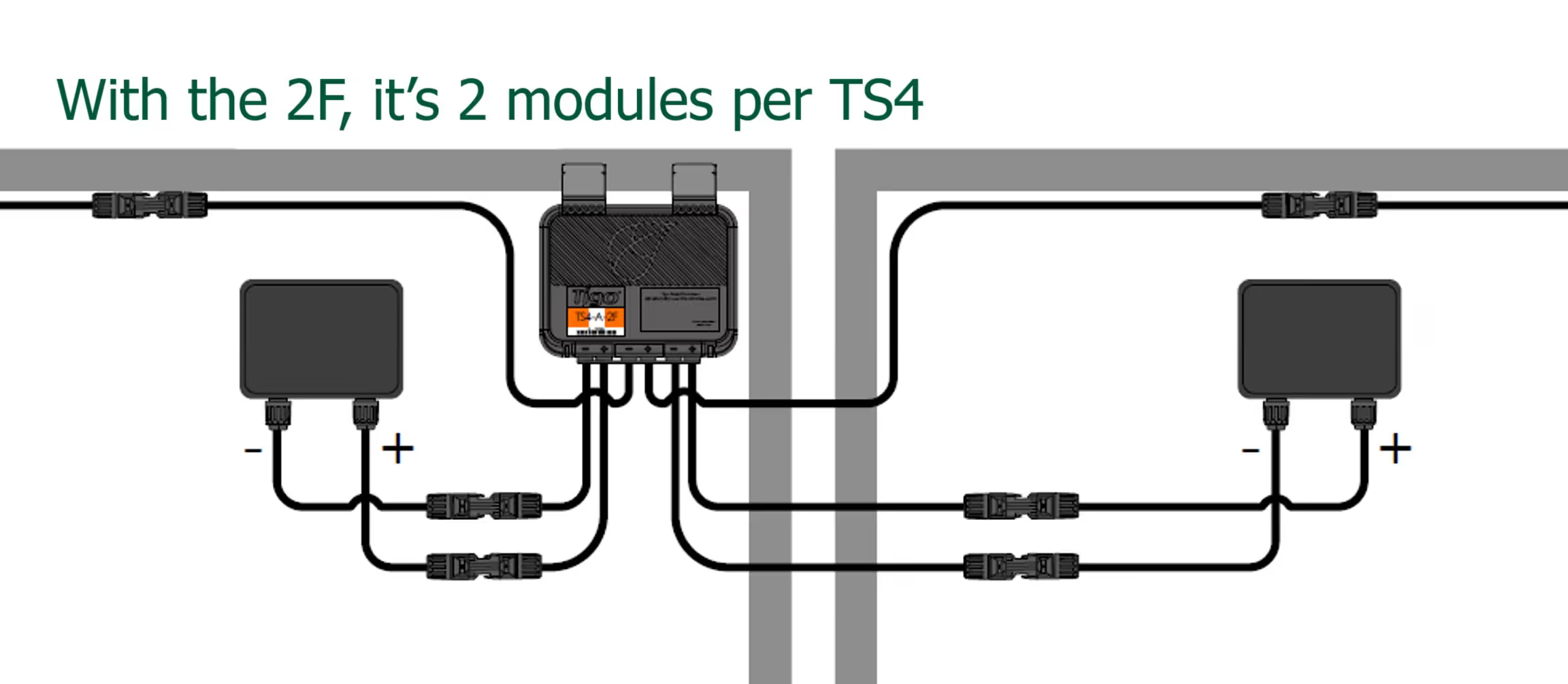
Now, after you connect the module to the TS4, then you can daisy chain the other TS4 together using the longer leads. And a lot of this is really intuitive, but I cover it anyways. If you're using the TS4-2F, well, then you've got two short leads, two long leads, but you still connect them in the same order. So, you always connect the short leads first, then the long ones. I cannot stress that enough.
I have a TS4 Certification Program, that I'm getting ready to launch, but I go through in a lot of detail step-by-step with a lot of questions that we get addressed in the certification program. So standby for that.
Tigo Enhanced
I want to talk a little about Tigo Enhanced inverters – they have a specific logo (see Figure 9). A Tigo Enhanced Inverter means that the RSS transmitter is integrated into that inverter. So be on the lookout for that. It really expedites the installation process and it's one less thing you have todo.
Tigo Enhanced is different than the PVRSS certified list of inverters that we have. And this is also required by code that they have to be tested together. So, the string inverters and the rapid shutdown devices have to be tested together. We've done that. We have an entire list of them on our website.
RSS Transmitter – single core
Now the single core, which means we have this RSS with a single core attached to it. Now, what we're looking at here is an integrated product and we do sell this enclosure but it's for the commercial product, but this could be any NEMA 3R/NEMA 4 enclosure that you have out there.
So, it mounts right on a din rail. The power supply comes with it. It's an AC to DC power supply. The reason we call it a single core is because we have just one core. And we have to bring power in – AC power on the bottom – and this power supply converts either 120- or 277-volt AC into the DC that the RSS transmitter needs.
Now we're showing down here that you put either the positive or the negative homeruns through the core, not both. And you have to do all of them. So, if you have three strings, then all three negatives will go through, or all three positives will go through.
Vivian (a webinar attendee) is asking what happens if you don't connect the short leads first and start daisy chaining as you go. Then you could damage the TS4. That's why we have this specific order. Great question.
RSS Transmitter – dual core
Now the dual core is the same thing. Now we do sell these separately. The dual core you’re probably looking at a large commercial string inverter, something pretty big. That’s typically what these are used for, but not always; we give you that flexibility. There are times when you may want to use two cores even on a single inverter.
Somebody is asking, “Can we use 240 to power of the unit?” Yes, you can.
RSS Signal Detector
We do have this little signal detector to help in commissioning. You just kind of wave it over the TS4 and it will tell you if the TS4 is detecting the keepalive signals. So, it can be used as a pretty handy troubleshooting device.
Design consideration
This is probably, in my opinion, probably the most important part. Crosstalk is this big thing now and it is a concern. What crosstalk means is that you have two different systems that are interfering with each other. So, the PLC from one inverter and RSS transmitter is interfering with a separate inverter and RSS transmitter.
And PLC is not new, it's been around a long time and particularly in like home automation. So, you have to separate the lines that the PLC is running on, and you can't have any external interference. But Tigo wasn't that great at giving everybody the details about this so we've really taken a round turn on this and we have some documentation and we're really trying to get people to understand the ways to mitigate this crosstalk.
Scenario 1: 1 inverter, 1 core
If you're using one inverter with one core, then there's no way you're going to have crosstalk. We're talking about per system.
Scenario 2: 1 inverter, 2 cores

If you're using one inverter in two cores, then you can put everything into the same conduit or cable tray, whatever you want to use, but do not route the strings from different transmitters in the same conduit. So, let's just say this is a big commercial inverter here, if you have another commercial inverter, then you cannot run those lines in the same conduit or cable tray, because they will start interfering with each other. And although you are only going to run either the positive or the negative homeruns through the RSS transmitter in the conduit and cable trays do not separate them, keep them together.
Scenario 3: 2 inverters, 1 core
Two inverters with one core. This is exactly the visual that I just talked about. Keep everything separate. And here's an example of the no-no where they have both outputs of the inverter going into the same conduit. So do this (left in Figure 12), not that (right in Figure 12). And we have a really detailed webinar on this, I went into excruciating detail on this and went through it very clearly.
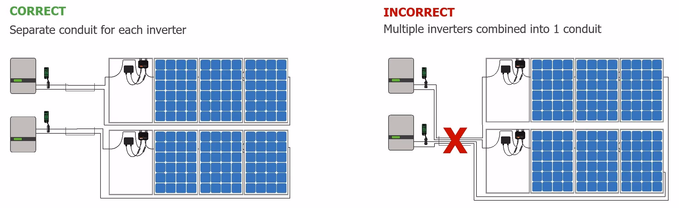
Scenario 4: 2+ inverters, 2 cores

So here we are with multiple strings, multiple arrays, multiple inverters. Again, just keep everything separate, just like that (left in Figure 13).Do not do this (right in Figure 13); you do not run everything together because you'll get the crosstalk.
It seems intuitive, but there are people in no fault of their own, that did not follow these instructions. These are requirements. If you don't follow our requirements, then you're going to have issues.
Best Practice – double up for long runs
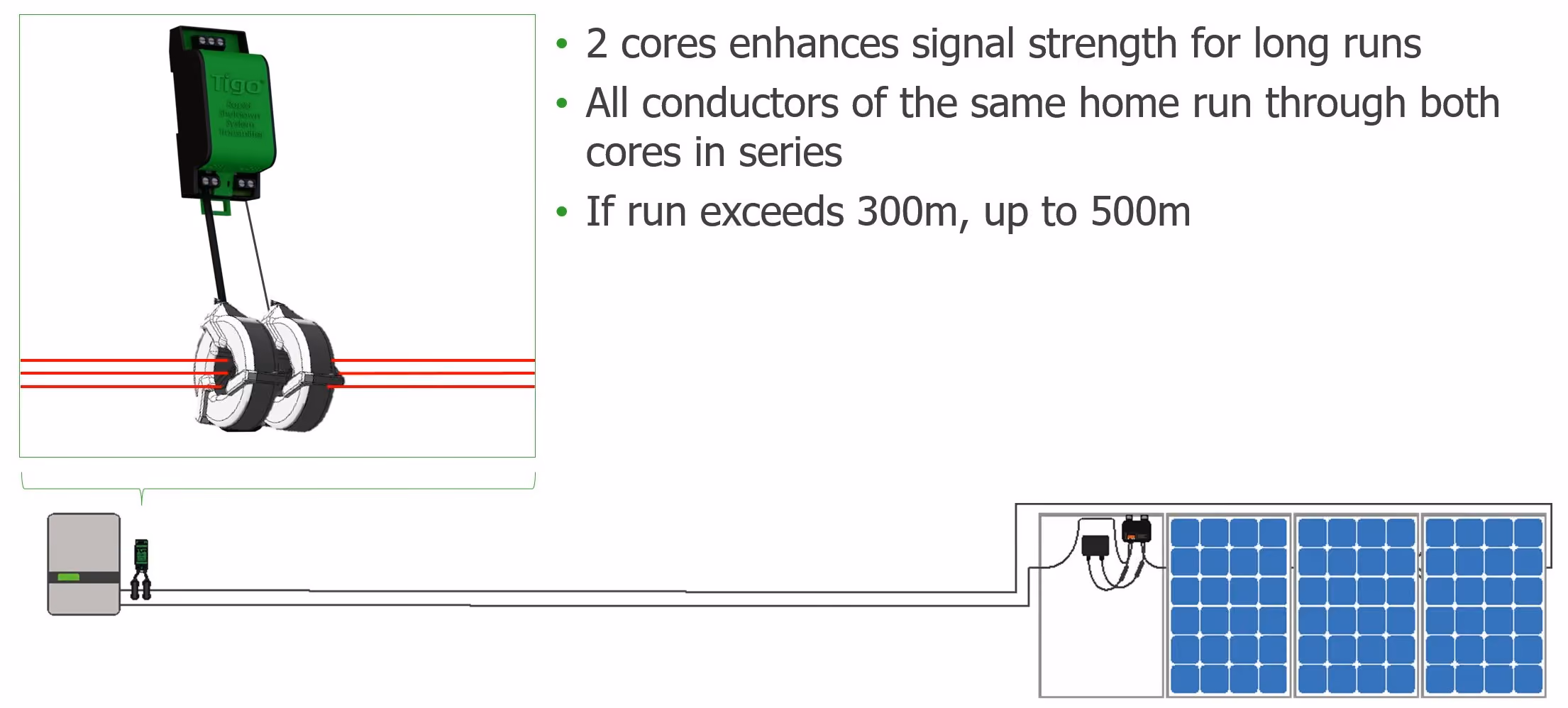
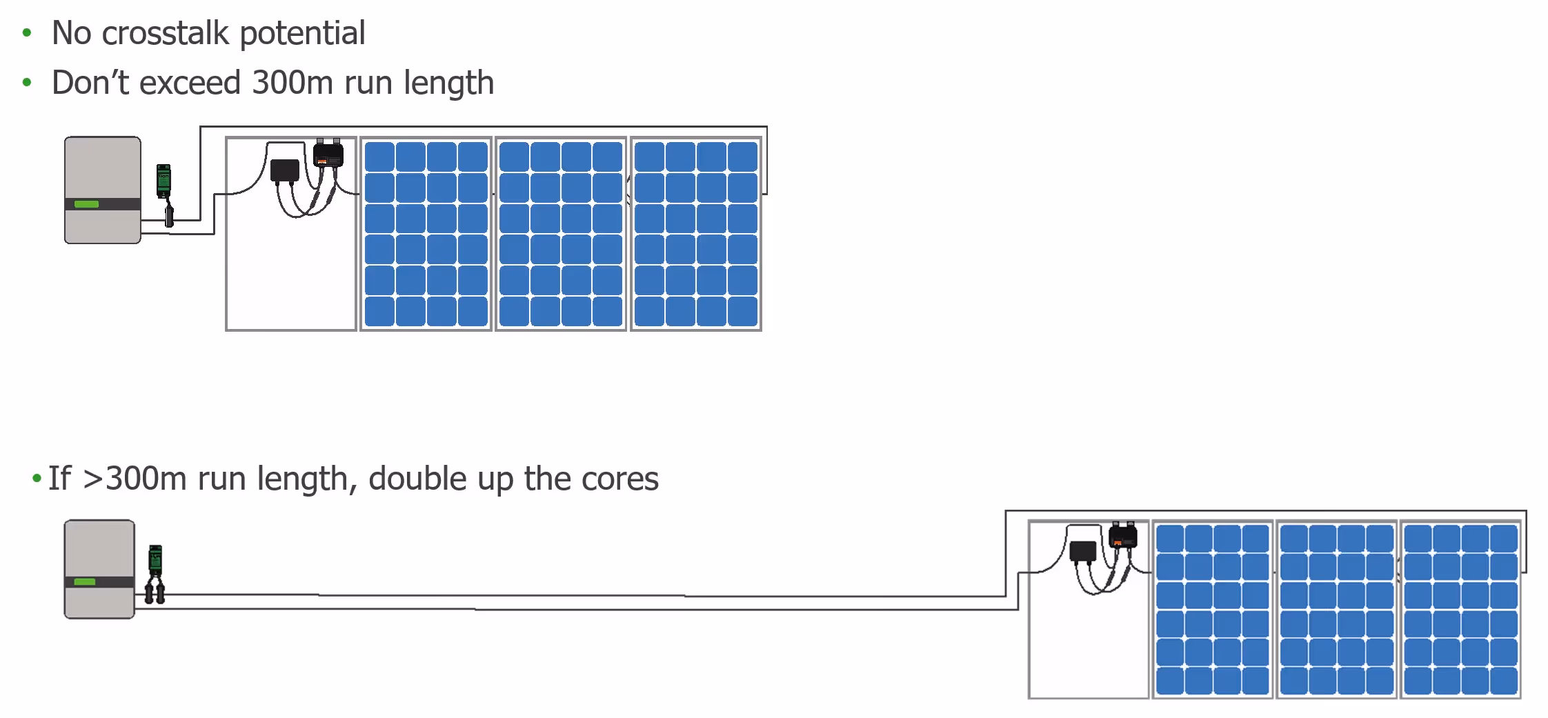
Now Figure 14 shows an example of what I was talking about if you have a single inverter, but you have to use two cores. So, you may have a DC run that exceeds 300 meters. So, we're definitely not talking about residential here, we’re probably talking about large commercial or utility. But if your run exceeds 300, then a single core can't induce a strong enough signal to get all the way down to the end of the 300 meters. If you double up on the course, then it will strengthen that signal, but we still limit the total distance with two cores to 500 meters.
Tigo Support
We have a support site. We have the community, which I really encourage people to go through. A lot of us lurk, a lot of us post there. So, if you have a question about these things, then go to the community and post it and we will jump in, and we'll help you.
And I mean, it ends up being this really cool thing and there could be somebody that beats one of us to the punch and answers your question first. So, it's just a people helping people thing in this industry. To leave a comment on this blog, click here.
