Blog
January 19, 2022
Design for Optimal Performance with TS4-A-F and 2F


NEC Rapid Shutdown
We're going to talk about the TS4-A-F. Sometimes I'll just refer to it as a TS4-F and then -2F.
Rapid shutdown is not a new concept here in the United States. Matter of fact, people are probably sick of hearing about it, but for half of you that may not know what it is, it is a National Electric Code (NEC) requirement.
In 2017, it really started driving the industry toward a module-level solution. We're going to talk about the instances where you will pretty much have to have something module level to comply with the requirements. There are spacing requirements, requirements that the inverter must meet, and there's these boundary requirements that we see throughout the code in this specific section that Tigo allows you to comply with.
Basically, you're going to need a module level solution that the string inverters just can’t help you comply with in every situation, but a module level component will.

Now most of the United States was on NEC 2017 or 2020 code cycle, but as you can see in Figure 1, there are some holdouts. However, pretty soon everybody is going to be under this umbrella. So, we're going to have everybody comply with these safety requirements, they’re important.
And it's not just the United States. We are deeply involved in Australia and particularly Taiwan. I just had a call last week about this, about a big system in Taiwan, and they are adopting this safety feature outside the United States.
Tigo’s F-Series Architecture

Let's take a look at the architecture. You're going to put a TS4 on each module, and it's very important that you connect the TS4 to the module frame.
Then, you connect the module to the TS4. Then, you connect the TS4 together. You want to make sure that you attach the module to the TS4. Then connect the TS4 together in a Daisy chain. Now, the TS4-A-F and -2F use PLC communication: power line communication (PLC).
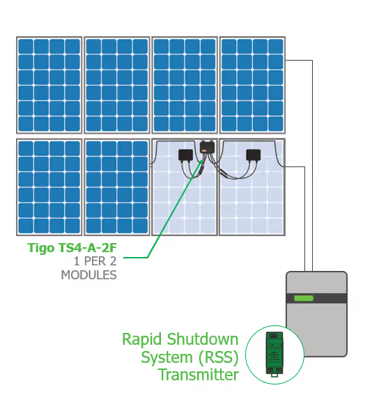
You don't need any other grounding wire for that. The TS4-2F, as you see in Figure 3, takes two modules into one MLPE. So, we're doubling up, but they both worked the same way. They still use PLC. You're just reducing the number of components up on the roof.
The Tigo Enhanced inverters have this rapid shutdown system, or our RSS transmitter, built into it. I've got 16 TS4 on my roof, I got a Sunny Boy 5,000 TLUS, and that Sunny Boy has this RSS built into it. So, we go to great lengths to make this as easy as possible.
The transmitter generates this heartbeat or this “keep alive” signal and it induces that signal using this CT or what we call a core. So, you're going to put the conductor, the PV array home run, through the core or home runs. And here I have the negative home run.
So, you're only going to use one of the polarities, either put all the positives or all the negatives through it and the transmitter induces this “keep alive” signal on to that conductor for powerline communication. As long as the TS4-F and -2F devices see this “keep alive” signal, then they allow array, voltage, and current to pass through them.
Now, when you secure power to the inverter, it automatically stops powering the RSS transmitter. The signal is not induced onto those PV source circuits, the TS4 shut off, and now you comply with that directive, easy peasy.
Specifications
Let's talk just a very quickly about the specs. This thing is rated up to 700 Watts. We're trying to keep up with those module manufacturers as they just get bigger and bigger. 16-90 volts is what the modules should be rated at 15 amps per channel. We're using the standard MC4 connector.
The -2F is just like having two of the TS4-F in one box and it's 500 Watts per channel, 1000 Watts total. The rest of the specs are the same so you're just able to have a “two-fer”.
System Example
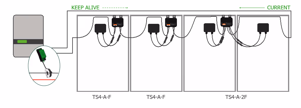
So, we're mixing and matching as shown in Figure 4 just as an example — the TS4-A-F and the 2F. We had the home runs coming and again, only one home run polarity per core. So, we have the keep alive signal going through these lines, the TS4 is like, “okay, there's a signal, cool, cool, cool. I'm going to optimize. I'm going to be waiting for somebody to tell me to shutoff.” And, when you lose power to the RSS transmitter, then we shut everything down and we comply with the boundary directives, with the voltage directives.
Now, there's also that voltage limit that we have to read. We have to be below 30-volts within 30 seconds, and we do assist in that. We help bleed that off so that you are under 30-volts in 30 seconds. A lot of string inverters are able to do this. They are able to discharge those capacitors, but we just allow you to do it for sure regardless of what brand you're using.
So, let's take a look at this communication method: power line communication. It is a low-cost solution, especially when you have an inverter with all of this stuff built into it. However, it is sensitive to interference. And then we get this cross modulation, which everybody is more familiar with the term “cross talk”, that can interfere with signal integrity. That's really what we want to do. We want to make sure that the signal from that RSS transmitter running through those lines is as strong and as undisturbed as possible.

So, here's the cross talk. You can get as complicated as you want, but it's basically interference between wires that degrades signal integrity. We just want to make sure that we have as strong a signal as possible. We're just seeing here the EMF flux lines are affecting that.
Design Recommendations
Let's look at some design considerations. There are four types of these use cases that I'm going to talk about. And the good news is that this cross talk isn't apparent, or it doesn't happen in all of these. So, it's not something that you need to stay awake at night worrying about. And by the end of this presentation, you're going to be able to figure out how to reduce the probability of cross talk in these systems anyway.
So here are the cases:
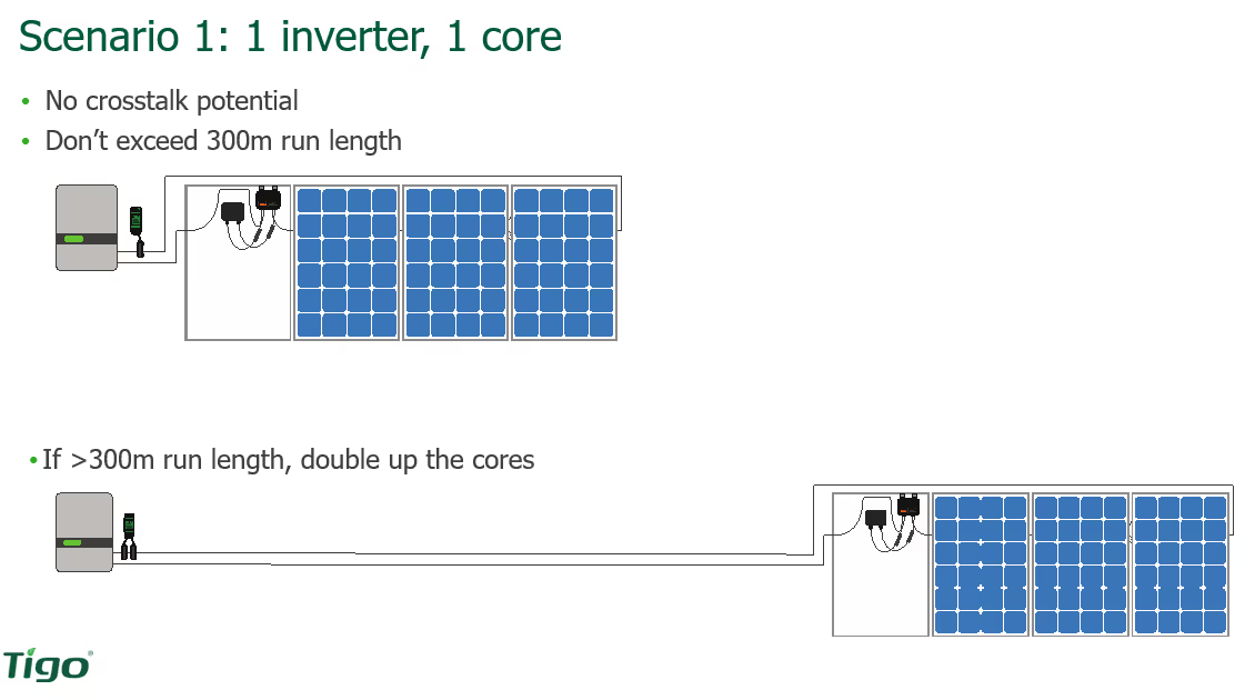
Scenario 1: One inverter with one core. That's what I have in my house. It has basically just one core that induces that to my 5,100 watt array. Then you have one inverter with two cores. Well, why would you need two cores? Well, you can put 10 conductors through one core. If you have one inverter in two cores, that's a lot of conductors, yeah?
We do tell you not to exceed 300 meters. So, if you do, if you do have a long home run, then what we recommend is doubling up on the cores so that you have two cores inducing that RSS signal, that keep alive signal.

Scenario 2: One inverter with two cores. What we see here is that it is okay to put all those surrogates in the same cable tray, in the same conduit. But we do not want to route strings from different transmitters in the same conduit though because you have two different signals going through there and they could affect each other. Also, do not separate the positive and negative of that string. So, you either have all the positives going through or you have all the negatives go through the core. Pick one, but don't mix and match.
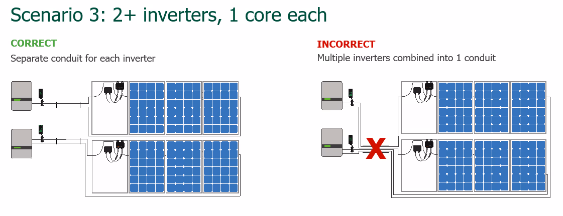
Scenario 3: Two inverters with one core. So here we're showing you what to do and then what not to do. So, if you have two inverters with one core, then you need to split those conduits. Do not run those two inverters, those strings from those two inverters, in the same conduit because now you have two different inverters, two different RSS transmitters, and that can interfere with each other. So, we show the right way to do it (left), and this is what we've seen people do that will cause an issue later on (right).

Scenario 4: Two inverters with two cores. We got some big inverters here, but the same rule applies. You separate them out so that they are in different conduit runs. If you have to put them in the same tray, they need to be at least eight inches apart, but we will get more into that here in a second.
So, this is the way to do it (left). This is how not to do it (right). Sometimes I'm a little reluctant on how not to do something because people sometimes get confused later out in the field or when they're on the designing room table and they're like, “Oh man, which one was I supposed to do?” So, we put a big red “X” here.
You'll be able to download this presentation. You'll have it with you and of course you can always call our apps engineers and be happy to talk to you about this. This is so crucial. A hundred percent of the people who use our apps engineers to make sure that they have a correct layout are successful a hundred percent of the time.
Cross Talk Mitigation
Let's talk about how to reduce or mitigate cross talk. We already talked about the conductors. We already talked about separating them out, but one other cool trick that you can do that we recommend is for each string, you have a positive and negative, right? If you twist those things together, then you'll have a better chance of eliminating that.
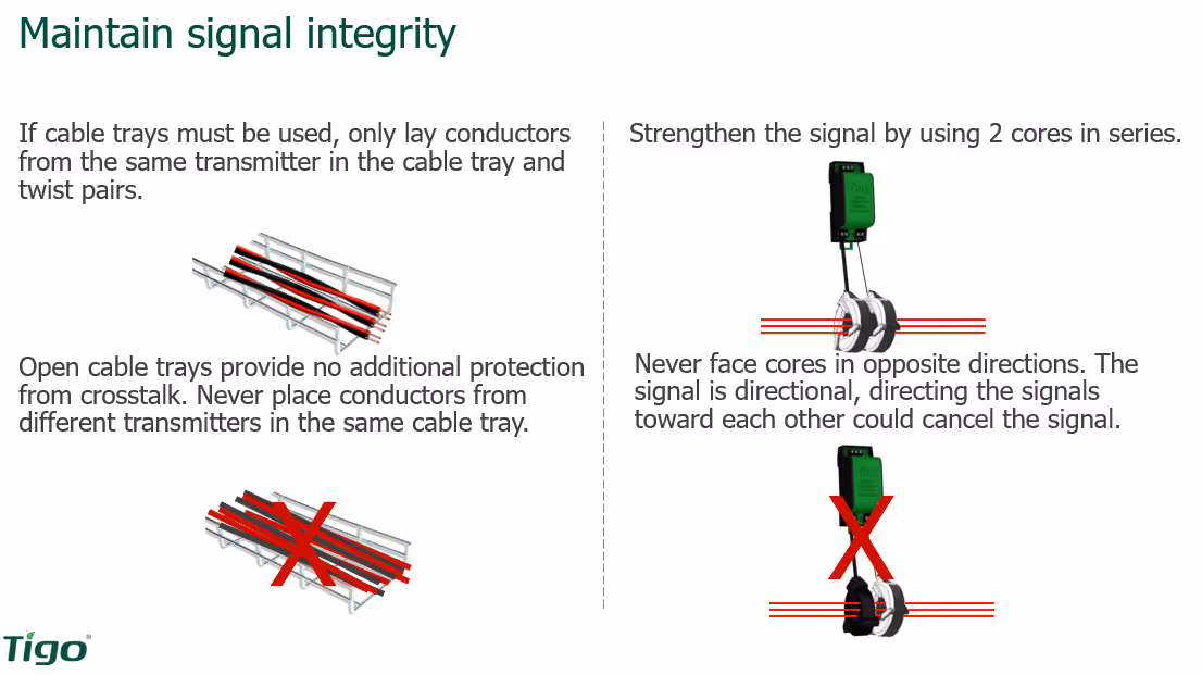
In Figure 6 we're showing the cable trays. These are really popular on commercial and I've seen them on utility scale. It's kind of cool, it's just underneath the array. They lay everything out in there. That's an option. So, we don't want to just throw them in the cable tray all willy nilly. We want to twist those ones. Separate them out as best we can.
If you do have long runs on the right in Figure 6, we're showing you how to double up on the cores. And you see that these cores are two colors and we just launched this not too long ago to make it easier for you guys to see which direction the cores go.
Also in Figure 6, you see the white side is on the left, the black side is on the right, and you want to make sure when you're feeding those conductors through the cores that you have the colors facing the same way. It’s very important.
Again, don't place conductors from different transmitters in the same cable tray because they're just going to cancel each other out.
Summary
So, we give you this rapid shutdown. It's a system level action. It's not for individual strings, it’s for the entire thing. So, keep your conduit separate. Please call our sales engineers. Please get ahold of us. You can get ahold of them at [email protected].
If you decide for whatever reason that PLC is not a good fit, if you don't want to go that direction, that's okay because we give you three other options. Most of which people gravitate toward the -O. They want the optimization, they want the module level monitoring, and they are able to comply with rapid shutdown. Now as this implies, TS4-A-O does not use PLC. It uses a different type of communication. It is wireless and we have a separate device that helps strengthen that wireless signal and that is definitely a different training.
We just launched our Tigo community not too long ago. That's a great place to go if you have a question. It's peers helping peers is the way we present it. So, if you have a question, maybe somebody else in the community that has Tigo experience, they jump right in. To leave a comment on this blog, click here.
